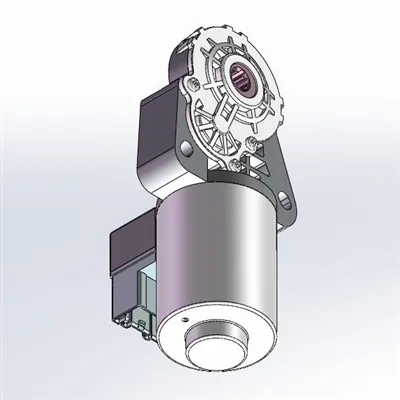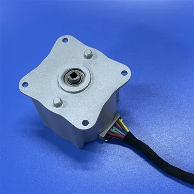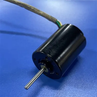


A brushless direct current motor (BLDC) is a type of DC motor that uses an electronic commutator instead of traditional mechanical brushes and commutators. Its core principle is to control the direction of the current in the stator windings through electronic circuitry, thereby achieving continuous rotor rotation.
The following analysis covers four dimensions: structure, working principle, control method, and advantageous applications:
Structural Composition
A brushless DC motor mainly consists of three parts:
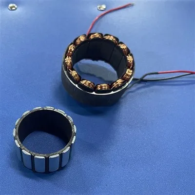
Stator: A core made of laminated silicon steel sheets wound with coils, which generates a rotating magnetic field when energized.
Rotor: Typically a permanent magnet (such as neodymium iron boron), it rotates through the interaction of the magnetic field.
Electronic Commutator: Composed of Hall effect sensors, position encoders, or sensorless algorithms (such as back EMF detection), it monitors the rotor position in real time and controls the commutation of the stator current.
Working Principle
Traditional DC motors rely on brushes and a commutator to mechanically switch the direction of current, while brushless motors achieve this process through electronic circuitry:
Rotor Position Detection: Hall effect sensors or encoders detect the rotor's magnetic pole position and transmit the signal to the driver.
Current Commutation Control: Based on the rotor position, the driver energizes the stator windings in a specific sequence (e.g., three-phase six-step), generating a rotating magnetic field. For example, a three-phase full-bridge drive circuit controls the phase difference of the U, V, and W phase currents through the combination of six power switches (MOSFETs or IGBTs), causing the magnetic field to rotate clockwise or counterclockwise.
Torque Generation: The rotor's permanent magnets chase the rotating magnetic field, generating continuous torque. For example, when the stator magnetic field rotates in 120° electrical angle steps, the rotor will synchronously follow, achieving smooth operation.
Control Methods
Square Wave Control (BLDC):The drive signal is a square wave, and the current commutation angle is fixed (e.g., 120° or 150°). Suitable for cost-sensitive applications with low speed requirements (e.g., fans, pumps).
Advantages: Simple control, low cost; Disadvantages: Large torque ripple, high noise.
Pulsed Sine Wave Control (PMSM): The drive signal is a sine wave, and the current phase is matched to the rotor position in real time. Suitable for high-precision, low-noise applications (e.g., CNC machine tools, robot joints).
Advantages: Smooth torque, high efficiency; Disadvantages: Complex control algorithm, high cost.
Sensorless Control: The rotor position is estimated using back electromotive force (Back-EMF) or a flux linkage observer, eliminating the need for physical sensors and reducing system cost and size. Commonly used in small household appliances (e.g., vacuum cleaners, drones).